G-series transmission
Controller power
The controller needs both a constant +12V and an ignition-switched +12V. The constant supply is required so that, after the ignition is turned off, the transmission can save its adaptations and shut down in a controlled way. This takes about 45 seconds, after which the controller powers itself off.
Wakeup
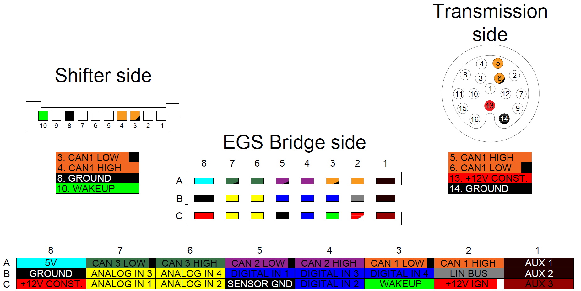
The controller's C3 WAKEUP pin is an output of the wakeup signal for the shifter. Connect it to pin 10 of the shifter. Never connect any WAKEUP pin directly to +12V!
Pinout
Controller side
| 8 | 7 | 6 | 5 | 4 | 3 | 2 | 1 | |
|---|---|---|---|---|---|---|---|---|
| A | 5V | CAN 3 low | CAN 3 high | CAN 2 low | CAN 2 high | CAN 1 low | CAN 1 high | Aux 1 |
| B | Ground | Analog in 3 | Analog in 4 | Digital in 1 | Digital in 3 | Digital in 4 | LIN bus | Aux 2 |
| C | +12V constant | Analog in 1 | Analog in 2 | Sensor GND | Digital in 2 | Wakeup | +12V ignition | Aux 3 |
Transmission side
| Pin | Signal |
|---|---|
| 5 | CAN 1 high |
| 6 | CAN 1 low |
| 13 | +12V constant |
| 14 | Ground |
Shifter side
| Pin | Signal |
|---|---|
| 3 | CAN 1 low |
| 4 | CAN 1 high |
| 8 | Ground |
| 10 | Wakeup |
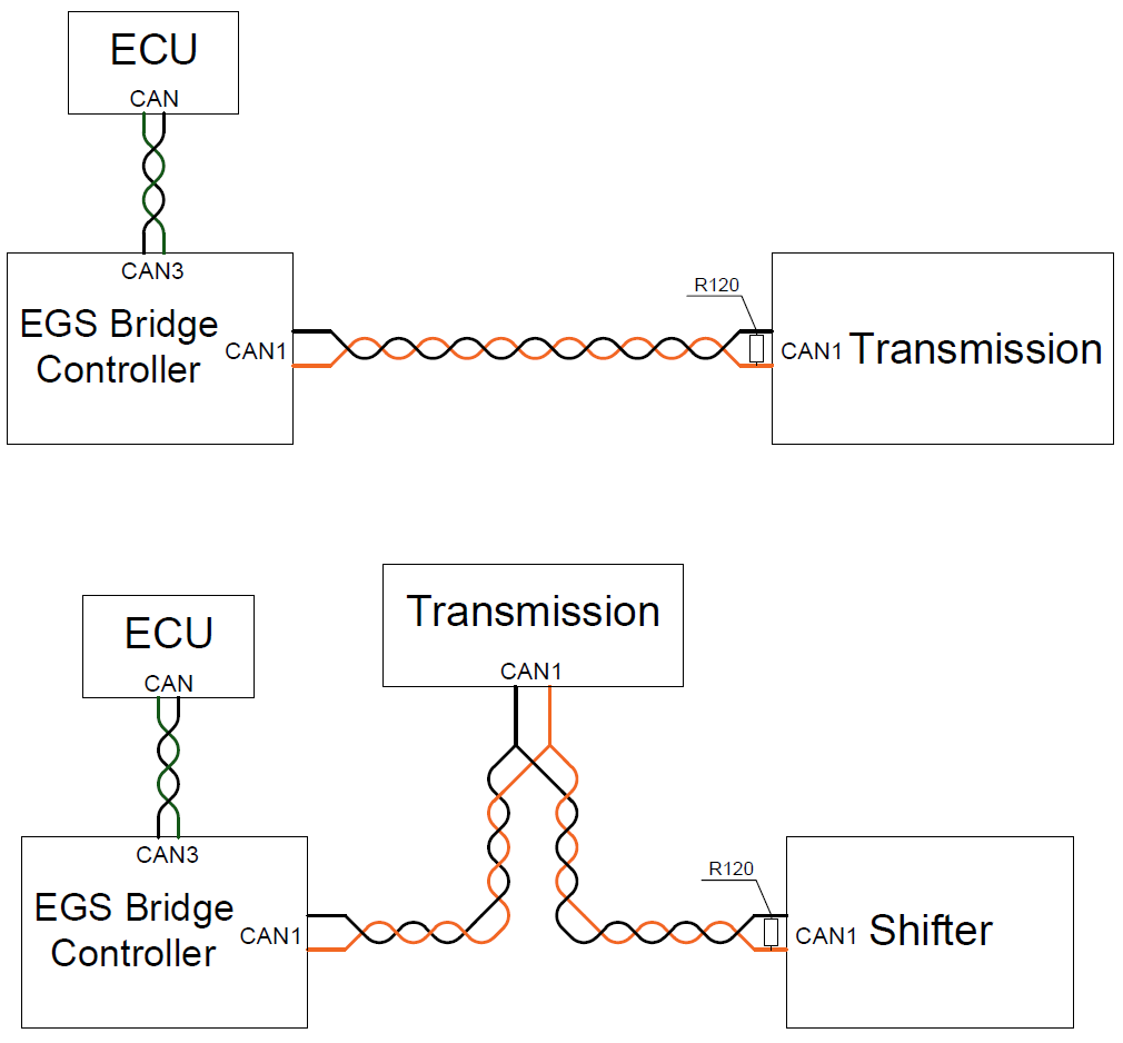
CAN bus wiring diagram